Aero Bumper Programme —
Nissan S-Chassis
Demonstrating full digital reconstruction: aligning custom aero body components against raw chassis point-cloud mesh, followed by production Class A surface modeling with clean patch layout and perfect reflection lines.
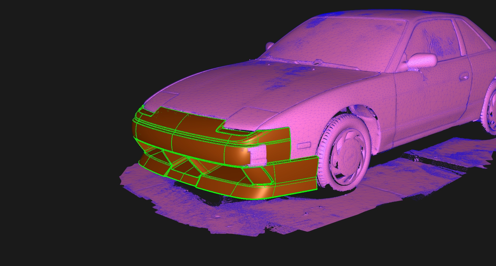
Scan Data vs. Engineered Surface
The raw 3D mesh (pink base) contains scanning noise, road distortion, and organic irregularities. The aero bumper model (gold CAD) is mathematically aligned to factory mounting points, hood shut-lines, pop-up light cutouts, and front fenders with sub-millimeter precision.
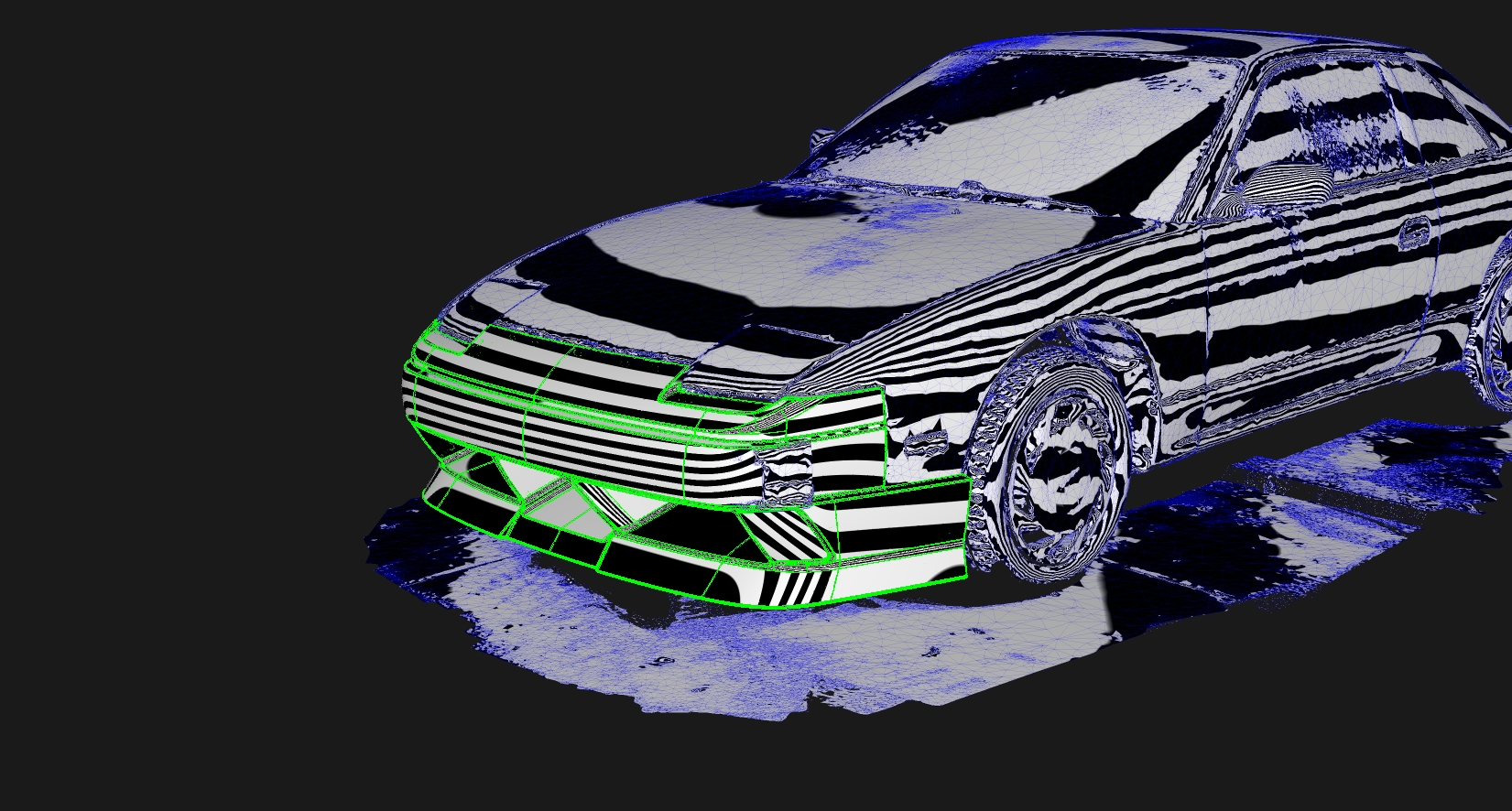
Zebra Reflection & Patch Layout
Zebra analysis verifies high-order G2/G3 continuity across compound air intakes, splitter steps, and wheel arch flares. Smooth, parallel stripes confirm no flat spots, pinches, or unwanted surface tension — ready for CNC mould milling and composite production.